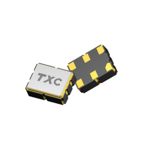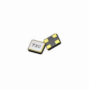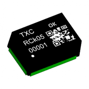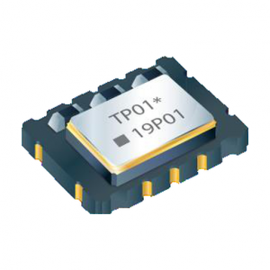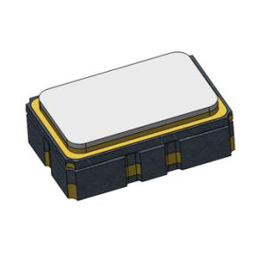
TXC 7P Series TCXO 5.0 x 3.2 mm 10 – 52 MHz
10 to 52 MHz precise TCXO in 5.0 x 3.2 x 1.8 mm, +/-0.10 to +/-0.28 ppm by temperature band, clipped sine or CMOS, 2.5 to 3.3 V, 6 or 10 pad.
Request Price & Availability
Pricing, lead time and bulk discounts are quoted per order — send us your part numbers and quantities and we will reply within one business day.
Email us for a quoteDescription
The 7P takes the electrical specification of TXC’s Precise TCXO family and puts it in a 5.0 x 3.2 x 1.8 mm package. For a board that is already tight, that is the whole argument: the same stability bands and the same output options as the larger 7N, with roughly half the footprint.
What is identical to the 7N and what is not
The electrical table is the same. Frequency range is 10 to 52 MHz, stability is +/-0.10 ppm from -20 to +70 C, +/-0.14 ppm from -40 to +85 C and +/-0.28 ppm from -40 to +105 C, load and supply each contribute +/-0.05 ppm, and the frequency tolerance after two reflows is +/-2.0 ppm. Supply is 2.5 to 3.3 V, current is 5 mA for the clipped sinewave output and 10 mA for CMOS, and start-up is 5 ms.
What changes is mechanical: 5.0 x 3.2 x 1.8 mm against 7.0 x 5.0 x 2.0 mm, and a pad count of 6 or 10 instead of 4 or 10. On a dense board that difference is often what decides whether the part fits next to the transceiver at all.
Layout consequences of the smaller package
Six pads is the minimum configuration; ten pads is the version that carries the AFC and output enable functions. Because the pads are closer together, the bypass capacitor called for in the datasheet has to be placed with more care than on the larger package, and the ground pad under the body should be tied to a quiet plane rather than to the digital return.
Output and control options
Clipped sinewave gives at least 0.8 Vp-p into 10 kohm with 10 pF, which suits a buffer input; CMOS swings 90 and 10 percent of Vcc into 15 pF with 6 ns edges. The AFC option pulls +5 to +12 ppm at 2.5 V control voltage and -5 to -12 ppm at 0.5 V, and the enable pin switches at 0.8 x Vcc and 0.2 x Vcc with a floating pin counting as enabled.
Aging, holdover and free-run
First-year aging is +/-1 ppm. The optional 24 hour holdover figure is +/-0.32 ppm after 48 hours of operation, and the free-run accuracy is +/-4.6 ppm over 20 years including calibration, temperature, supply and load variation, reflow shift and aging. Those two numbers are the ones to quote when a customer asks how long a node can run without a network reference.
Verified ordering codes
The codes below were each checked against a live distribution listing and carry the frequency, package, CMOS output at 3.3 V and the catalogued +/-0.28 ppm stability figure. The suffix is not decoded here because it bundles output type, stability band and packaging; a frequency outside this list is quoted against the code that matches the band the design needs.
| Part number | Frequency | Package |
|---|---|---|
| 7P-10.000MBP-T | 10.000 MHz | SMD 5.0 x 3.2, 6 pad |
| 7P-19.200MBP-T | 19.200 MHz | SMD 5.0 x 3.2, 6 pad |
| 7P-25.000MBP-T | 25.000 MHz | SMD 5.0 x 3.2, 6 pad |
| 7P-26.000MBP-T | 26.000 MHz | SMD 5.0 x 3.2, 10 pad |
| 7P-30.720MBP-T | 30.720 MHz | SMD 5.0 x 3.2, 6 pad |
| 7P-38.400MBP-T | 38.400 MHz | SMD 5.0 x 3.2, 6 pad |
All 6 codes are sourced to order; availability and lead time are confirmed with each quotation. Send the frequency, the temperature band and the annual quantity to leon@vexelora.com.
Specification summary
| Frequency range | 10 – 52 MHz, fundamental |
|---|---|
| Stability, -20 to +70 C | +/-0.10 ppm |
| Stability, -40 to +85 C | +/-0.14 ppm |
| Stability, -40 to +105 C | +/-0.28 ppm |
| Stability vs load, +/-5% | +/-0.05 ppm |
| Stability vs supply, +/-5% | +/-0.05 ppm |
| Frequency tolerance, after two reflows | +/-2.0 ppm |
| Slope over temperature | +/-50 ppb/C (-40 to +85 C), +/-100 ppb/C (-40 to +105 C) |
| Supply voltage | 2.5 to 3.3 V +/-5% (2.8 V and 3.3 V typical) |
| Current, clipped sine / CMOS | 5 mA / 10 mA max |
| Output, clipped sine | 0.8 Vp-p min into 10 kohm // 10 pF |
| Output, CMOS | 90% / 10% of Vcc into 15 pF, rise and fall 6 ns max |
| Duty cycle | 40 to 60% |
| Start-up time | 5 ms max to 90% of final amplitude |
| AFC pull range (option) | +5 to +12 ppm at VC = 2.5 V, -5 to -12 ppm at VC = 0.5 V |
| Aging, first year | +/-1 ppm |
| Holdover stability, 24 h (option) | +/-0.32 ppm after 48 h operation |
| Free-run accuracy, 20 years | +/-4.6 ppm including calibration, temperature, supply, load, reflow and aging |
| Package | 5.0 x 3.2 x 1.8 mm, 6 or 10 pad |
Typical applications
- Small cell radio boards with limited area
- Optical module and line card timing
- Portable instrumentation
- Wireless infrastructure reference clocks
Related TXC timing products
- TXC frequency control products at Vexelora
- TXC 7N Series TCXO 7.0 x 5.0 mm
- TXC OG Series OCXO 9.8 x 7.6 mm, +/-5 ppb grade
- TXC OH Series OCXO 7.0 x 5.0 mm
- TXC 7C-25.000MBB-T 25 MHz CMOS clock oscillator
Send the frequency, output type and temperature band to leon@vexelora.com for a quotation.
Specifications
| Attributes | Value |
|---|---|
| Brand |
TXC |
| Condition |
New / Original |
| Packaging |
Standard export carton |
| Lead Time |
Availability and lead time confirmed with each quotation |
| Warranty |
12 months |
| Series |
7P (Precise TCXO) |
| Output Frequency |
10 – 52 MHz |
| Frequency Stability vs Temperature |
+/-0.10 ppm (-20 to +70 C), +/-0.14 ppm (-40 to +85 C), +/-0.28 ppm (-40 to +105 C) |
| Supply Voltage |
2.5 to 3.3 V +/-5% (2.8 V / 3.3 V typical) |
| Output Type |
Clipped sinewave or CMOS |
| Operating Temperature |
-40 to +105 C maximum range, see stability bands |
| Package |
5.0 x 3.2 x 1.8 mm, 6 pad or 10 pad |
| Current Consumption |
5 mA max clipped sine, 10 mA max CMOS |
| AFC |
Option, +5 to +12 ppm at VC = 2.5 V, -5 to -12 ppm at VC = 0.5 V |
| Aging |
+/-1 ppm first year |
| Start-up Time |
5 ms max |