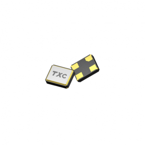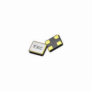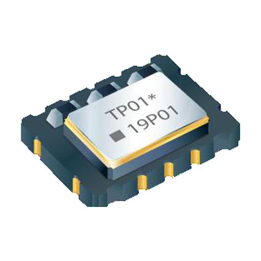
TXC 7N-26.000MBP-T TCXO 26 MHz CMOS 3.3 V 7.0 x 5.0 mm
TXC 7N-26.000MBP-T, 26 MHz CMOS precise TCXO in the 7.0 x 5.0 x 2.0 mm ten-pad package, 2.5 to 3.3 V, catalogued at +/-0.28 ppm. Sourced to order.
Request Price & Availability
Pricing, lead time and bulk discounts are quoted per order — send us your part numbers and quantities and we will reply within one business day.
Email us for a quoteDescription
7N-26.000MBP-T is a fixed-frequency part: 26.000 MHz, CMOS output, a 7.0 x 5.0 x 2.0 mm ten-pad package and a 2.5 to 3.3 V supply. It is one of ten 7N codes whose frequency has been confirmed against a live distribution listing, so there is nothing to configure when quoting it.
Why 26 MHz keeps turning up
26 MHz sits in an awkward but useful place in the frequency plan. It is high enough that the phase-noise skirt falls away from the carrier before it reaches a GNSS baseband’s tracking bandwidth, and low enough that the divider chain back to the receiver’s sampling clock stays short. GNSS front ends commonly take a 26 MHz reference alongside 16.368 MHz, and the same frequency appears as the transceiver reference in cellular modules, which is why a single reel of 26 MHz parts can serve two different product lines on the same bench.
The arithmetic is straightforward: 26 MHz divides by 26 to give 1 MHz, by 52 to give 500 kHz, and multiplies up to 1575.42 MHz with a fractional ratio that most integrated synthesisers handle in one stage. That is the practical reason the frequency survives in designs that could otherwise choose anything in the 10 to 52 MHz band.
Stability: read the band, not the headline
The 7N family does not have one stability number, and quoting the wrong one is the most common way to lose a design review. TXC specifies +/-0.10 ppm from -20 to +70 C, +/-0.14 ppm from -40 to +85 C and +/-0.28 ppm from -40 to +105 C on the same electrical table. The catalogued figure for this code is +/-0.28 ppm, which is the 105 C column carried over as the worst case; a board that only ever sees -40 to +85 C is running inside a tighter number than the label suggests.
Load and supply each add +/-0.05 ppm at +/-5%, and the frequency tolerance after two reflow cycles is +/-2.0 ppm, so the part has to be measured after assembly rather than trusted from the reel. First-year aging is +/-1 ppm, which is the figure that matters for a receiver that has to stay on frequency across a deployment cycle rather than across a temperature sweep.
Output and control pins
The CMOS output swings to 90 and 10 percent of Vcc into 15 pF with rise and fall times of 6 ns or less, at up to 10 mA. Duty cycle stays between 40 and 60 percent. Start-up reaches 90 percent of final amplitude within 5 ms, which is fast enough that a receiver does not need a separate hold-off timer on the reference.
Ten pads is the version that carries both options: an AFC input that pulls +5 to +12 ppm at 2.5 V control voltage and -5 to -12 ppm at 0.5 V, and an output enable pin that switches at 0.8 and 0.2 times Vcc with a floating pin counting as enabled. If the design does not need either, the four-pad body in the same footprint is the cheaper route and the electrical table is unchanged.
Layout in the 7 x 5 footprint
At 7.0 x 5.0 x 2.0 mm the part is large enough that the bypass capacitor sits close to the supply pad without contesting space with the pad row, and the ground pad under the body should be tied to a quiet plane rather than to the digital return. Keep the output trace away from the AFC node: the AFC line is a high-impedance input and will pick up switching noise from any trace that runs parallel to it for more than a few millimetres.
Ordering this code
The MPN fixes the frequency, the package and the output type. If the design needs the 85 C band rather than the 105 C band, or a clipped sinewave output for a buffer input, the order moves to a different 7N code and is quoted against that requirement. Parts are sourced to order; availability and lead time are confirmed with each quotation. Send the annual quantity and the temperature band to leon@vexelora.com.
Specification summary
| Nominal frequency | 26.000 MHz |
|---|---|
| Series / package | 7N, 7.0 x 5.0 x 2.0 mm, 10 pad SMD |
| Output type | CMOS |
| Supply voltage | 2.5 to 3.3 V +/-5% |
| Current consumption | 10 mA max, CMOS output |
| Operating temperature | -40 to +85 C |
| Frequency stability, -20 to +70 C | +/-0.10 ppm |
| Frequency stability, -40 to +85 C | +/-0.14 ppm |
| Frequency stability, -40 to +105 C | +/-0.28 ppm |
| Stability vs load, +/-5% | +/-0.05 ppm |
| Stability vs supply, +/-5% | +/-0.05 ppm |
| Frequency tolerance, after two reflows | +/-2.0 ppm |
| Aging, first year | +/-1 ppm |
| Start-up time | 5 ms max to 90% of final amplitude |
| Duty cycle | 40 to 60% |
| Output swing, CMOS | 90% / 10% of Vcc into 15 pF, rise and fall 6 ns max |
| AFC pull range (option) | +5 to +12 ppm at VC = 2.5 V, -5 to -12 ppm at VC = 0.5 V |
Typical applications
- GNSS receiver reference
- Cellular module transceiver reference
- Portable navigation and tracking devices
- Radio front-end local oscillator
Related TXC timing parts
- TXC 7N Series TCXO, full family and bands
- TXC frequency control products at Vexelora
- 7N-38.400MBP-T, 38.400 MHz
- 7N-40.000MBP-T, 40.000 MHz
- 7P-30.720MBP-T, 30.720 MHz
- 7P-38.400MBP-T, 38.400 MHz
- TXC OG Series OCXO, +/-5 ppb grade in 9.8 x 7.6 mm
Send the frequency, temperature band and annual quantity to leon@vexelora.com for a quotation. Availability and lead time are confirmed with each quotation.
Datasheet
Full electrical tables and package drawings are in the official manufacturer datasheet: Download the TXC 7N-26.000MBP-T datasheet (PDF).
Specifications
| Attributes | Value |
|---|---|
| Brand |
TXC |
| Condition |
New / Original |
| Packaging |
Standard export carton |
| Lead Time |
Availability and lead time confirmed with each quotation |
| Warranty |
12 months |
| Series |
7N |
| Nominal frequency |
26.000 MHz |
| Package |
7N, 7.0 x 5.0 x 2.0 mm, 10 pad SMD |
| Output type |
CMOS |
| Supply voltage |
2.5 to 3.3 V |
| Frequency stability |
+/-0.28 ppm (catalogued); +/-0.10 / 0.14 / 0.28 ppm by band |
| Operating temperature |
-40 to +85 C |