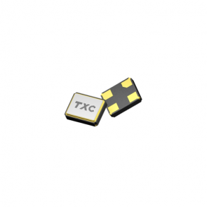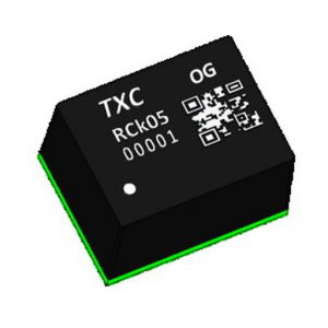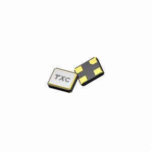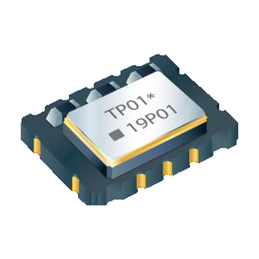
TXC 7N-40.000MBP-T TCXO 40 MHz CMOS 3.3 V 7.0 x 5.0 mm
TXC 7N-40.000MBP-T, 40 MHz CMOS precise TCXO in the 7.0 x 5.0 x 2.0 mm ten-pad package, 2.5 to 3.3 V, catalogued at +/-0.28 ppm. Sourced to order.
Request Price & Availability
Pricing, lead time and bulk discounts are quoted per order — send us your part numbers and quantities and we will reply within one business day.
Email us for a quoteDescription
7N-40.000MBP-T is a 40.000 MHz CMOS TCXO in the 7.0 x 5.0 x 2.0 mm ten-pad 7N package, supplied from 2.5 to 3.3 V and catalogued at +/-0.28 ppm. The frequency and package are confirmed against a live distribution listing.
Where 40 MHz is used
40 MHz is the reference frequency that many 2.4 GHz radio SoCs expect on their crystal or clock input, because it divides cleanly to the 1 MHz and 500 kHz steps that the synthesiser uses and still multiplies up to the 2.4 GHz band with a single integer ratio. The same frequency appears in wireless audio links and in industrial PHY designs where the clock has to survive a cable run and a temperature swing at the same time.
A radio reference does not need oven-grade stability, but it does need stability that holds across the full operating range rather than at 25 C. That is the gap a TCXO fills: a plain clock oscillator is typically tens of ppm over temperature, while the 7N holds a few tenths of a ppm, which is what keeps the carrier inside its allocated mask without a recalibration step in production.
What the catalogue figure means
The electrical table carries three rows for stability: +/-0.10 ppm from -20 to +70 C, +/-0.14 ppm from -40 to +85 C and +/-0.28 ppm from -40 to +105 C. This code is catalogued at +/-0.28 ppm, the widest of the three, and the operating temperature is catalogued at -40 to +85 C. Read together, the label is the conservative number and the band actually ordered is what fixes the guaranteed figure.
On top of temperature there are the smaller terms: +/-0.05 ppm for a five percent load change, +/-0.05 ppm for a five percent supply change, +/-2.0 ppm of frequency tolerance after two reflow cycles and +/-1 ppm of first-year aging. A radio that has to hold its channel after a year in the field is spending the aging term, not the temperature term.
Output and control
CMOS output swings 90 and 10 percent of Vcc into 15 pF with 6 ns edges at up to 10 mA, with duty cycle between 40 and 60 percent and start-up inside 5 ms. The ten-pad body is the version with the optional AFC input, +/-5 to +/-12 ppm at 0.5 to 2.5 V control, and an output enable pin that floats enabled. For a radio that never needs trimming, the four-pad body in the same footprint removes both options and keeps the electrical table intact.
Board-level notes
At 40 MHz the output edge is fast enough that the trace to the radio should be treated as a transmission line once it passes a few centimetres, and the series termination the radio datasheet calls for should be placed at the source rather than at the load. Keep the AFC node short and away from the RF ground stitching: it is a high-impedance input and it will rectify any stray field it picks up.
Ordering this code
The MPN fixes 40.000 MHz, CMOS, ten pads and the catalogued stability. Other frequencies in the 10 to 52 MHz range, a clipped sinewave output or a different band are separate 7N codes. Parts are sourced to order; availability and lead time are confirmed with each quotation. Send the frequency plan and annual quantity to leon@vexelora.com.
Specification summary
| Nominal frequency | 40.000 MHz |
|---|---|
| Series / package | 7N, 7.0 x 5.0 x 2.0 mm, 10 pad SMD |
| Output type | CMOS |
| Supply voltage | 2.5 to 3.3 V +/-5% |
| Current consumption | 10 mA max, CMOS output |
| Operating temperature | -40 to +85 C |
| Frequency stability, -20 to +70 C | +/-0.10 ppm |
| Frequency stability, -40 to +85 C | +/-0.14 ppm |
| Frequency stability, -40 to +105 C | +/-0.28 ppm |
| Stability vs load, +/-5% | +/-0.05 ppm |
| Stability vs supply, +/-5% | +/-0.05 ppm |
| Frequency tolerance, after two reflows | +/-2.0 ppm |
| Aging, first year | +/-1 ppm |
| Start-up time | 5 ms max to 90% of final amplitude |
| Duty cycle | 40 to 60% |
| Output swing, CMOS | 90% / 10% of Vcc into 15 pF, rise and fall 6 ns max |
| AFC pull range (option) | +5 to +12 ppm at VC = 2.5 V, -5 to -12 ppm at VC = 0.5 V |
Typical applications
- 2.4 GHz radio SoC reference
- Wireless audio and video links
- Industrial sensor nodes
- PHY and MAC clocking
Related TXC timing parts
- TXC 7N Series TCXO, full family and bands
- TXC frequency control products at Vexelora
- 7N-26.000MBP-T, 26.000 MHz
- 7N-38.400MBP-T, 38.400 MHz
- 7P-30.720MBP-T, 30.720 MHz
- 7P-38.400MBP-T, 38.400 MHz
- TXC OG Series OCXO, +/-5 ppb grade in 9.8 x 7.6 mm
Send the frequency, temperature band and annual quantity to leon@vexelora.com for a quotation. Availability and lead time are confirmed with each quotation.
Datasheet
Full electrical tables and package drawings are in the official manufacturer datasheet: Download the TXC 7N-40.000MBP-T datasheet (PDF).
Specifications
| Attributes | Value |
|---|---|
| Brand |
TXC |
| Condition |
New / Original |
| Packaging |
Standard export carton |
| Lead Time |
Availability and lead time confirmed with each quotation |
| Warranty |
12 months |
| Series |
7N |
| Nominal frequency |
40.000 MHz |
| Package |
7N, 7.0 x 5.0 x 2.0 mm, 10 pad SMD |
| Output type |
CMOS |
| Supply voltage |
2.5 to 3.3 V |
| Frequency stability |
+/-0.28 ppm (catalogued); +/-0.10 / 0.14 / 0.28 ppm by band |
| Operating temperature |
-40 to +85 C |